
Abstract: The coil is the heart of the transformer and the center of transformer conversion, transmission and distribution. To ensure the long-term safe and reliable operation of the transformer, the following basic requirements must be ensured for the coil of the transformer:
a. Electrical strength. In long-term operation of transformers, their insulation (the most important of which is the insulation of the coil) must be able to reliably withstand the following four voltages, namely lightning impulse overvoltage, operating impulse overvoltage, transient overvoltage and long-term operating voltage. Operating overvoltages and transient overvoltages are collectively referred to as internal overvoltages.
b. Heat resistance. The heat resistance strength of the coil includes two aspects: First, under the action of the long-term working current of the transformer, the service life of the coil insulation is guaranteed to be equal to the service life of the transformer. Secondly, under the operating conditions of the transformer, when a short circuit suddenly occurs, the coil should be able to withstand the heat generated by the short-circuit current without damage.
c. Mechanical strength. The coil should be able to withstand the electromotive force generated by the short-circuit current without damage in the event of a sudden short circuit.
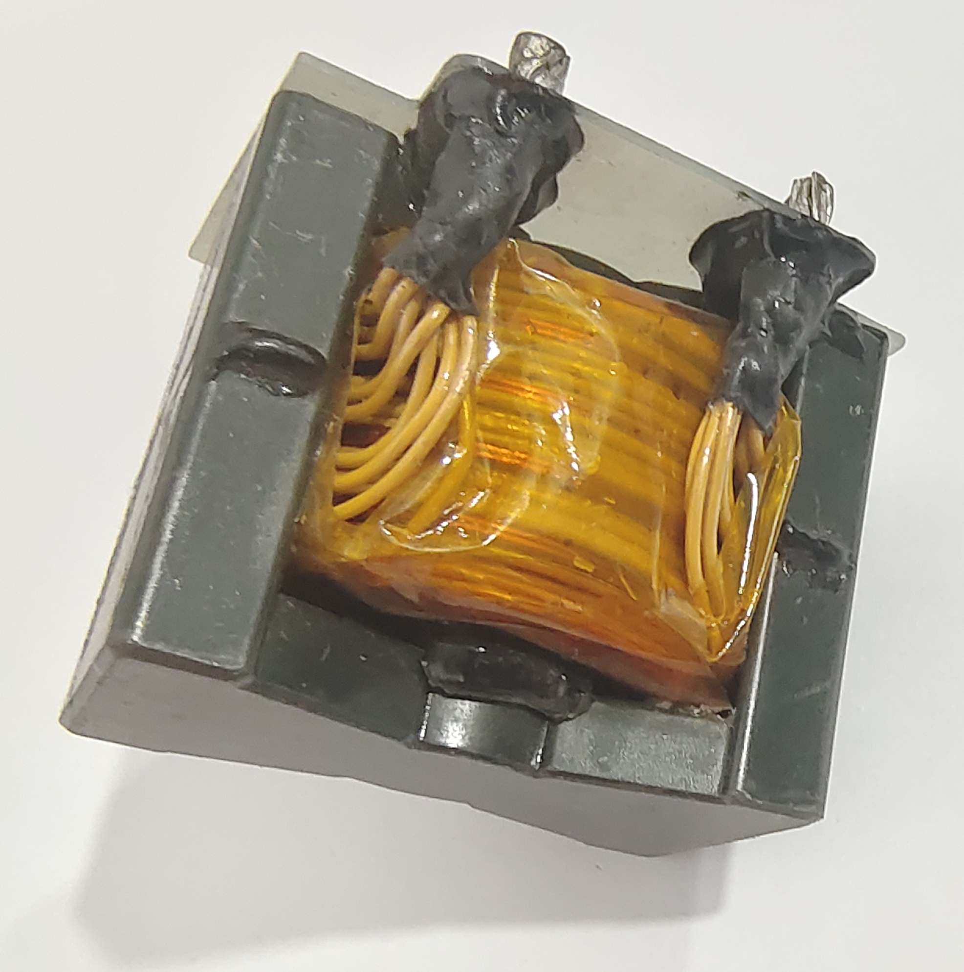
1. Transformer coil structure
1.1. The basic structure of the layer coil. Each layer of the lamellar coil is like a tube, winding continuously. Multilayers are made up of multiple such layers arranged concentrically, and the interlayer wires are usually controlled continuously. Double-layer and multi-layer coils have a simple structure.
High production efficiency, commonly used in small and medium-sized oil-immersed transformers of 35 kV and below. Double-layer and four-layer coils are generally used as low-voltage coils of 400V, and multilayer coils are generally used as low-voltage or high-voltage coils of 3kV and above.
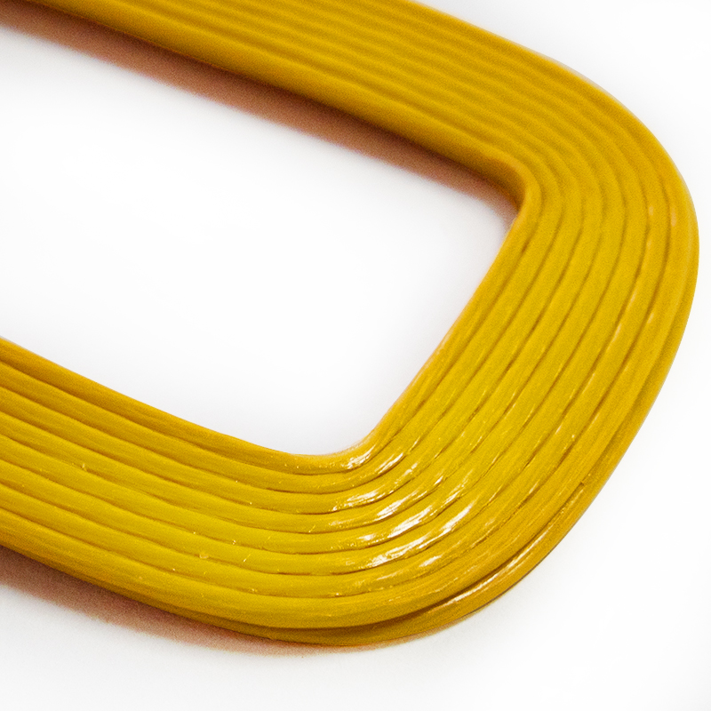
1.2. The basic structure of the pie coil pancake rolls are generally wound with flat wires, and the line segments are like cakes. It has good heat dissipation performance and high mechanical strength, so it has a wide range of applications.
Pie coils include a variety of continuous, tangled, internally shielded, spiral and so on. Interlaced and “8″ coils used in special transformers are also pie types. The basic structure of several commonly used pie coils is briefly classified as follows:
1.2.1. The number of continuous coil segments of continuous coil is about 30~140 segments, generally even (end outlet) or multiples of 4. (middle or end outlet) to ensure that the first and last ends of the coil are pulled out at the same time outside or inside the coil. The number of turns of the outer coil can be an integer, the number of turns of the inner coil is usually the number of fractional turns, and the coil can have taps or no taps as needed.
1.2.2. Tangled coils. The commonly used entanglement coil is to use double cake as the entanglement unit, generally known as double cake tangling. The oil passage inside the unit is called the outer oil passage, and the oil channel between the units is called the inner oil passage. Both parts of a unit are even-numbered circles, which is called even-number entanglement. It’s all bizarre spins, known as simple tangles. The first segment (reverse segment) is a double segment, and the second (positive segment) is a single segment, which is called double single entanglement. The first paragraph is single, and the second paragraph is double, which means single and double tangled. The entire coil is made up of tangled units, called full tangles. There are only a few tangled units at the end (or both ends) of the entire coil, and the rest are continuous line segments, called tangled continuity.
1.2.3、Inner screen continuous coil. The inner shielded continuous type is formed by inserting a shielded wire with increased longitudinal capacitance in a continuous line segment, so it is also called the insertion capacitor type. It looks like a mess. The number of turns per inserted network cable can be freely changed as needed. The inner shield coil uses the same components as the continuous type. There is no operating current on the screen, so thin wires are usually used.
The conductor through which the operating current passes is continuously wound, which reduces a large number of sonotrodes compared to the entangled type, which is the first advantage of the inner shielded type. The number of turns inserted into the screen wire can be freely adjusted, so that the longitudinal capacitance can be adjusted as needed, which is the second advantage of the inner shielding type.
1.2.4. Spiral coil spiral coil is used for low-voltage, high-current coil structure, and its wires are connected in parallel. All parallel winding lines overlap to form a line cluster, and the line group advances once in each circle, called a single helix. All the wires are wound in parallel to form two overlapping wire cakes, and the wires of the two wire cakes pushed forward in each turn are called double helixes. According to this, there are triple helixes, quadruple spirals, etc.
2. Analysis of common problems in the coil winding process.
During the winding of transformer coils and the production of insulating parts, various quality problems will occur. The quality problems that have occurred in our factory in the past year can be summarized into the following three categories.
2.1. Coordination and collision problems. Component matching problems occur very frequently in the production process of transformers in our factory, and they cannot be avoided from the outside to the inside, from the metal structure workshop to the coil workshop. As soon as such problems occur, the manufacturing process stops, resulting in a serious loss of quality.
For example: 1TT.710.30348 In the inspection of the winding group of the super-large engineering company, it was found that the inner support width of the cardboard barrel tube for low-voltage coil was not properly designed. The opening of the gasket is 21 mm and the width of the support should be 20 mm. The drawing width shown in the figure is 27 mm. In response to such problems, the author believes that the following aspects should be taken to reduce the possibility of collision-type quality problems.
a. When designing, you can preview the layout of common parts related to the design component to facilitate inspection during design.
b. For oil flap, corner ring, gasket and other accessories, the quantity should be carefully checked during the design verification process, and the correct universal parts should be selected for the accessories.
c. Make the inspection record of the machine head and its supporting parts.
d. Update the quality control table of typical problem cases, design, check and check item by item, and increase the inspection of the group’s internal quality control table.
e. Update the part matching table in the group, design, check and carefully fill in and check the part matching table.
2.2. Calculation error problem. Calculation errors are the worst mistakes designers make. If this occurs, it will not only hinder the manufacturing process of the transformer, but also cause rework of components, resulting in huge losses.
Example: When assembling the voltage regulating coil of this product at TT.710.30331, it was found that the pressure regulating cardboard tube was 20mm higher than the required value. In response to such problems, it is believed that the following measures should be taken to reduce the possibility of collision-type quality problems.
a. Draw the parts proportionally, and if they are measurable, try not to calculate them by hand. b. Write the widget calculation applet to calculate the size. c. Organize local typical diagrams and typical K tables, and formulate the use guide selected in the design.
2.3. Drawing annotation problems. Drawing annotation issues also accounted for a large proportion of quality issues in 2014. Such problems are caused by the lack of care of designers, and the consequences are sometimes very serious. Some parts were remade due to labeling issues, with serious consequences.
Example: Section 710.30316 During the production of this product, it was found that the upper and lower electrostatic plate drawings of the high voltage coil showed a non-static plate.
The physical electrostatic plate has a barrier layer that prevents the operator from proceeding to the next process without confirmation. In response to such problems, the author believes that the following aspects should be taken to reduce the possibility of collision-type quality problems.
Formulate drawing dimension specifications (such as marking in the order of parts, such as whole, groove, hole, etc.), eliminate excess dimensions on the drawing, and make dimensional filling inspection records (according to the processing order).
b. In the process of design and proofreading, carefully check the dimensions of each group of parts to ensure that the content drawn on the drawing is consistent with the content of the annotation, and ensure that the dimensional information is fully expressed.
c. Incorporate the drawing annotation problem into the quality control table for control.
d. Improve the level of standardization and reduce errors caused by design omissions, drawing annotation and other problems. The above is my understanding of the design of coil drawings in more than 2 years of internal design of transformers.
Post time: Apr-08-2023